Topic Summaries
Ray diagrams
Energy and power
Renewable energy and efficiency
Charge, current, and electric fields
Potential difference and resistors
Electricity
Volume and gases
States of matter and heat capacity
Radiation
Nuclear fusion and fission
Forces
Velocity and acceleration
Gravity and Newton's Laws
Moments and elastic potential
Stopping, braking, and momentum
Properties of waves
Electromagnetic waves
Refraction and lenses
Light, colour, and ray diagrams
Absorbing and emitting infrared radiation
Magnetic fields
Motor effect, generator effect, and transformers
Science skills: Experimental procedures
Science skills: Presenting and using data
Science skills: Measuring results
- Ray diagrams are used to determine the position, size, orientation, and nature (real or virtual) of an image formed by a lens by tracing the paths of light rays from an object.
- Objects are typically assumed to be placed on the principal axis, with the object extending vertically above the axis to simplify the construction of the diagram.
- The top of the image is located at the point where the refracted rays from the top of the object intersect (or appear to diverge from) after passing through the lens.
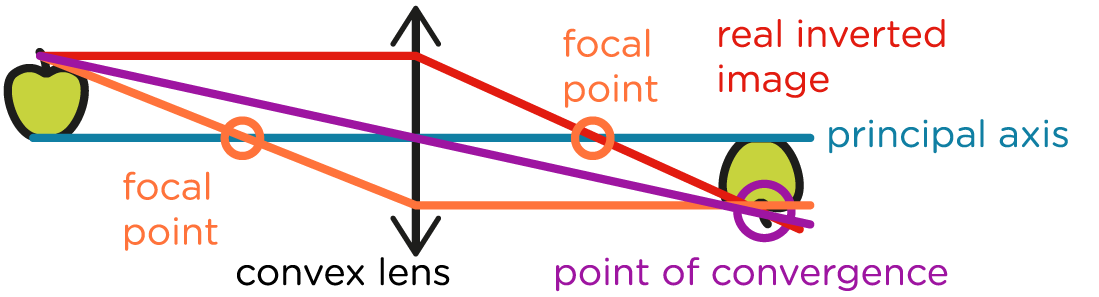
- To construct a ray diagram for a convex lens, three principal rays are usually drawn from the top of the object:
- A ray parallel to the principal axis travels to the lens and is refracted through the focal point on the opposite side.
- A ray through the centre of the lens (optical centre) continues in a straight line without deviation.
- A ray directed toward the focal point on the object's side of the lens is refracted by the lens to emerge parallel to the principal axis.
- The nature of the image depends on the object's distance from the lens:
- If the image forms on the opposite side of the lens from the object, it is a real image (can be projected on a screen).
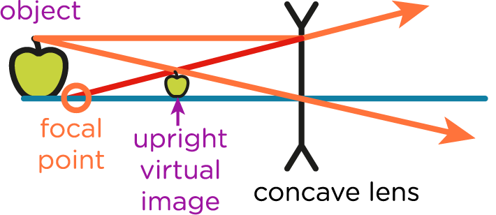
- If the rays diverge and the image appears to form on the same side as the object, it is a virtual image (cannot be projected).
- The orientation of the image depends on where the rays converge:
- If they meet below the principal axis, the image is inverted.
- If they meet above the axis (as in virtual images), the image is upright.
- The size of the image compared to the object can be magnified, diminished, or same size, depending on the object's distance from the lens relative to the focal length.
Unlock Ray diagrams
Subscribe to SnapRevise+ to get immediate access to the rest of this resource.
Premium accounts get immediate access to this resource.