Topic Summaries
Logic gates and symbols
COMPUTER SYSTEMS: Systems architecture
COMPUTER SYSTEMS: Computer systems
COMPUTER SYSTEMS: Memory and storage
COMPUTER SYSTEMS: Number systems
COMPUTER SYSTEMS: Encoding and compression
COMPUTER SYSTEMS: Networks
COMPUTER SYSTEMS: The internet
COMPUTER SYSTEMS: Network topologies
COMPUTER SYSTEMS: Wired and wireless networks, protocols, and layers
COMPUTER SYSTEMS: Threats to computer systems and networks
COMPUTER SYSTEMS: Operating systems and utility software
COMPUTER SYSTEMS: Impact of technology on society
ALGORITHMS AND PROGRAMMING: Computational thinking
ALGORITHMS AND PROGRAMMING: Algorithm representation
ALGORITHMS AND PROGRAMMING: Types of data
ALGORITHMS AND PROGRAMMING: Programming fundamentals
ALGORITHMS AND PROGRAMMING: Programming techniques
ALGORITHMS AND PROGRAMMING: Producing robust programs
ALGORITHMS AND PROGRAMMING: Testing programs
ALGORITHMS AND PROGRAMMING: Designing, creating, and refining algorithms
ALGORITHMS AND PROGRAMMING: Boolean logic
ALGORITHMS AND PROGRAMMING: Programming languages
ALGORITHMS AND PROGRAMMING: Python
ALGORITHMS AND PROGRAMMING: Artificial Intelligence (AI)
- Boolean logic is used in computer systems to make decisions using only two states: 1 = True, and 0 = False.
- It is based on logic gates and Boolean operators: AND, OR, and NOT. These are used in logic diagrams, truth tables, and real-world decision-making in code and digital circuits.
| Operator | Description | Symbol (logic gate) |
| AND | True only if both inputs are true | 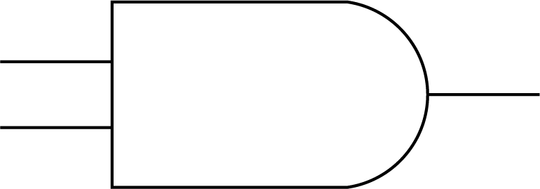 |
| OR | True if at least one input is true | 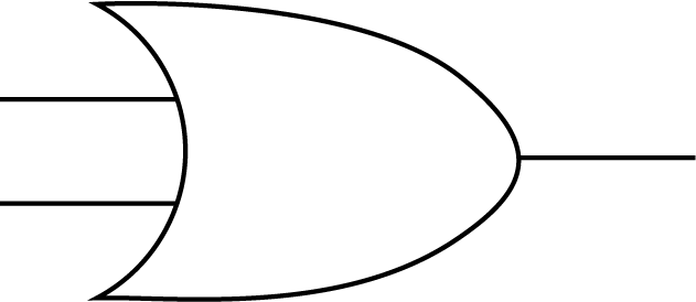 |
| NOT | Reverses the input (True becomes False, and vice versa) | 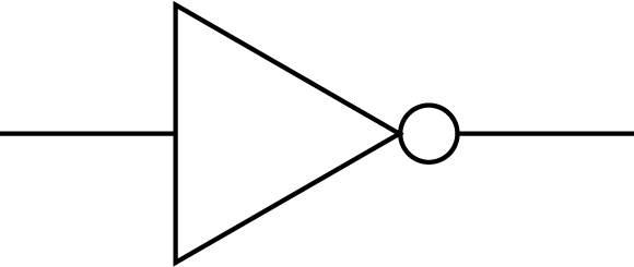 |
- Logic diagrams show how logic gates are connected. You need to be able to:
- Recognise AND, OR, and NOT symbols.
- Draw diagrams from expressions.
- Trace how inputs flow through each gate.
- Tip: work from left to right and evaluate gate-by-gate when solving a diagram.
- Alternative notations you may see:
| Symbol | Meaning |
| ∧ | AND |
| ∨ | OR |
| ¬ | NOT |
| T | True (1) |
| F | False (0) |
Unlock Logic gates and symbols
Subscribe to SnapRevise+ to get immediate access to the rest of this resource.
Premium accounts get immediate access to this resource.